The Brief
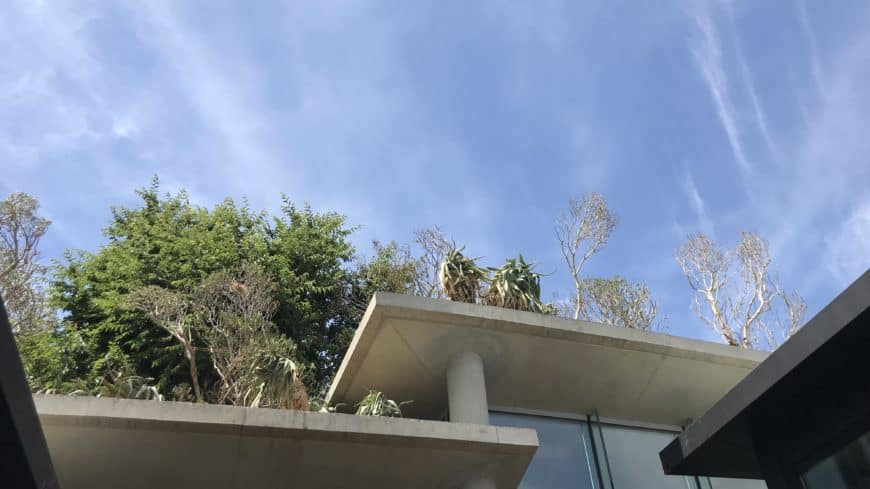
To construct a 44.4m long raking, curved, off-shutter concrete roof for a curved passage linking living spaces for a very unique residential development. The roof comprised two 16,5m and one 11,4m raking, curved sections with ends stacked on top of each other, and this whole stacked roof structure was suspended on slender 300mm concrete columns up to 4,9m high. Each section of the roof also had a recess on top for planting, with all the necessary drainage installed in the 300mm concrete columns.
Options…
The first challenge with this roof was the columns. Firstly, the columns had to be erected in the correct position, to the nearest millimetre. Then, if a 4,8m high column is out of plumb by 0,1deg, the top of the column is off by 8mm. By the time you are 0,3deg out of plumb, which you still cannot see with the naked eye, you are off by 24mm at the top…
The first option was to erect the columns as best as possible and then build the formwork for the roof with timber, by hand. With this method, we would be able to compensate for any tolerance on the concrete columns but to construct curved, raking formwork, almost five meters up in the air for 44m long would take too long and the risk of getting it wrong, would just be too high.
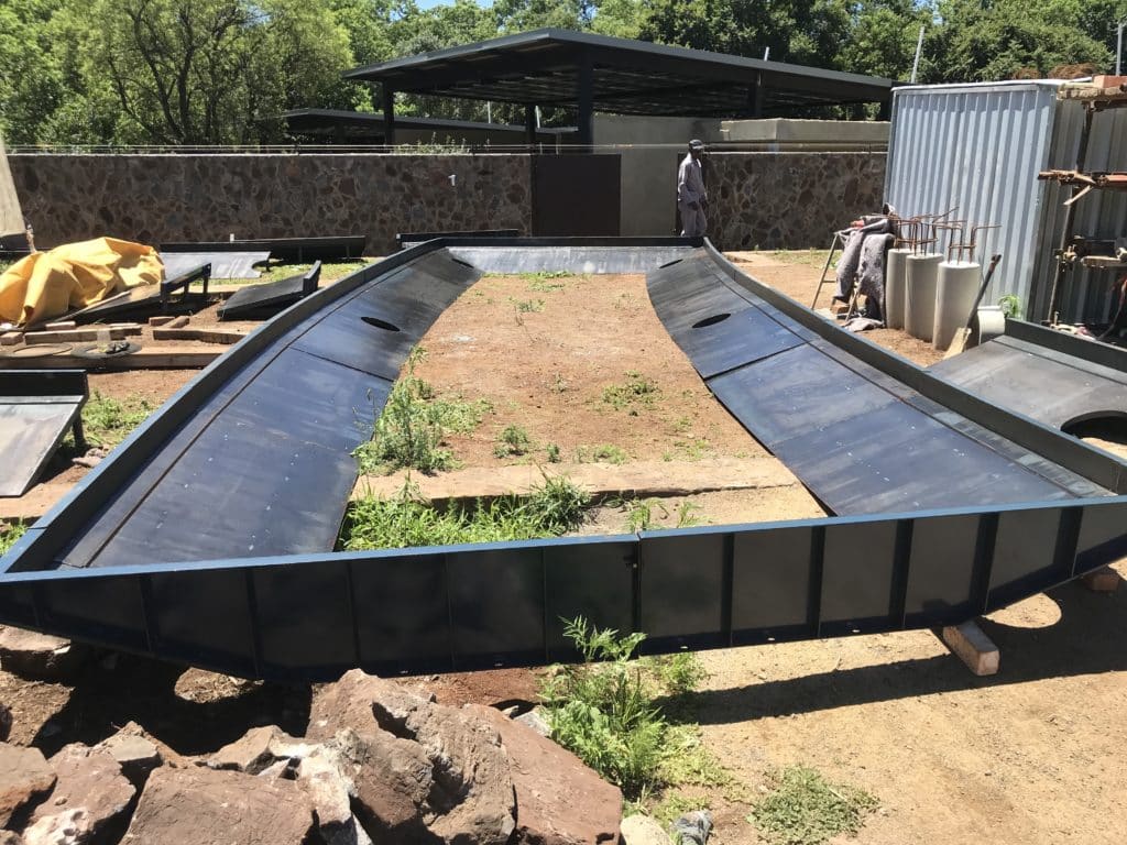
Due to the complexity of the shape, I wanted to go with prefabricated steel formwork. The benefit of the three, identical stacked roofs were that I could re-use the formwork three times, which brought the cost for the steel formwork within a justifiable price for the client. The big benefit of the steel formwork was the speed with which we could erect the formwork and the accuracy we would have. I just had to figure out how to allow for a degree of tolerance on the columns.
Getting the columns plumb
Obviously the first thing to focus on is how to get the columns as accurate as possible. Due to the whole passage curving, no two columns lined up so to set up a reference grid was not going to work. To survey each column after erection was going to be too expensive and time-consuming. In the end, I decided to use a 1,6m long digital inclinometer (a fancy name for an electronic spirit level). With this inclinometer, we could measure up to 0.1deg accurate, so we would get close, within the constraints of the steel column formwork.
I further had special brackets made up to attach push-pull props to the column formwork. What made these brackets special was that the hole in the brackets for the push-pull prop pin, had a 0,2mm tolerance, so it was a very tight fit. I wanted to be sure that there was no play between the formwork and props once the formwork was plumbed.
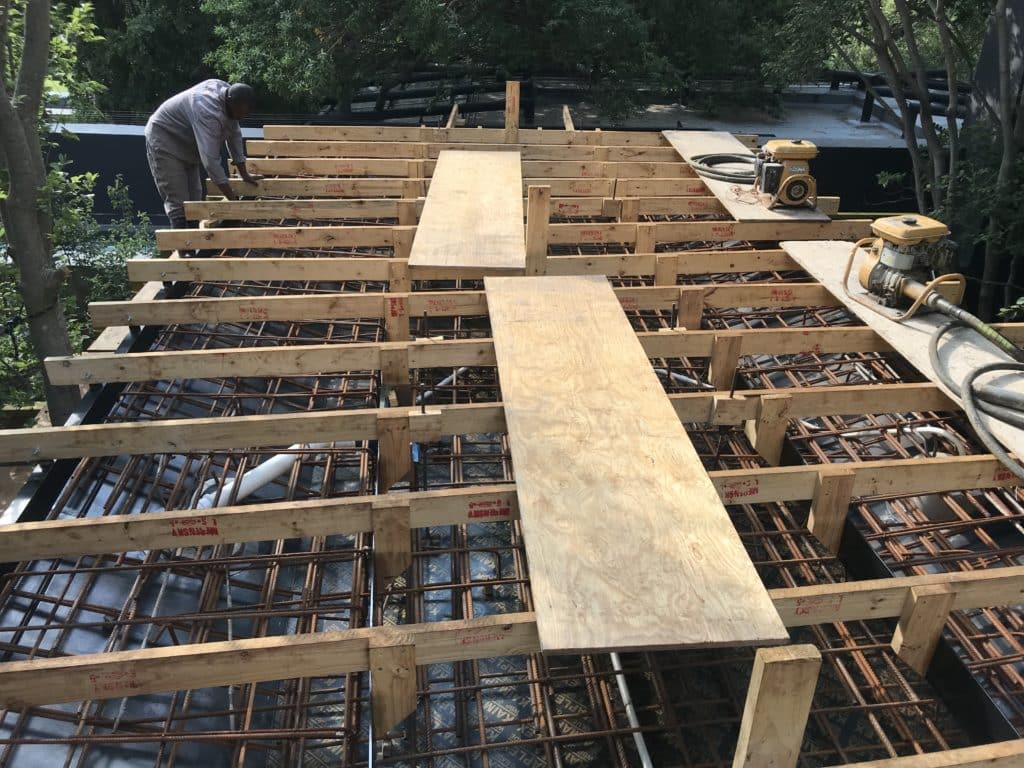
The second way in which we allowed for as much tolerance on the columns as possible, was to make the openings, where the columns would go through the steel formwork quite a bit bigger than what was required for the column diameter. This would allow room to get the steel formwork to line up with the columns and the second benefit was that I had steel ‘compensation rings’ made up with which I could finish very tight up to the concrete columns and seal them, to prevent any concrete from the roof, leaking onto the columns. Due to the complexity of the assembly, we would not have been able to get to the underside of the formwork to clean up any leakage after the pour and by the time we removed the formwork the damage to the columns would have been done, so I wanted to reduce the risk of leakage as much as possible.
Modular assembly
Although the profile of the three roof sections was the same, the length and ends of each roof section were different. The symmetry in the design made it possible to fabricate the steel formwork to be completely modular making that all three roofs could be formed with one set of formwork with interchangeable parts.
While I figured out how to make the formwork modular, I want to give a big shoutout to the guys at Staluform who did a great job at designing the detail of the formwork. It was very well thought out, well constructed and easy to work with.
How to form a curving soffit ?
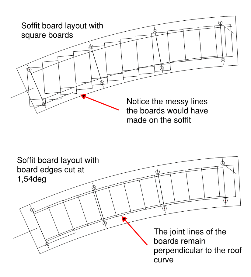
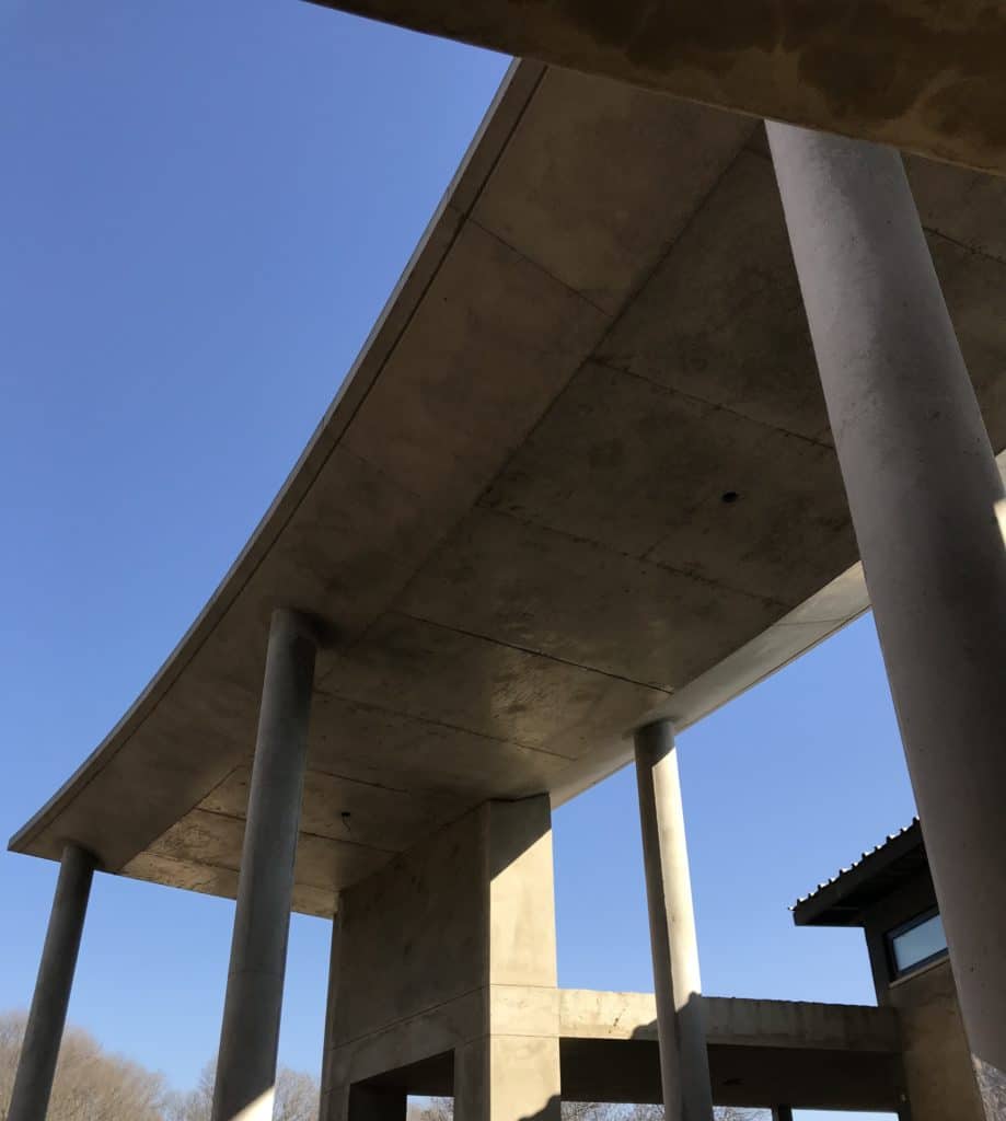
The soffit was formed using resin face board. What worried me when I drew out the formwork (I always do a board layout for concrete soffits) was that the joint lines on square boards, would not follow the curve of the roof. With the small infill pieces that would be required and the joint lines being almost random to the soffit lines, it just looked wrong.
So I worked out the angle with which the perpendicular line to the curve would change with each board, which was 1,54deg per board and then had all the resin face boards waterjet cut at a 1,54deg angle on one side with the other side remaining square. The result was that the joint lines on the soffit of the slab were always perpendicular to the edge of the curved roof.
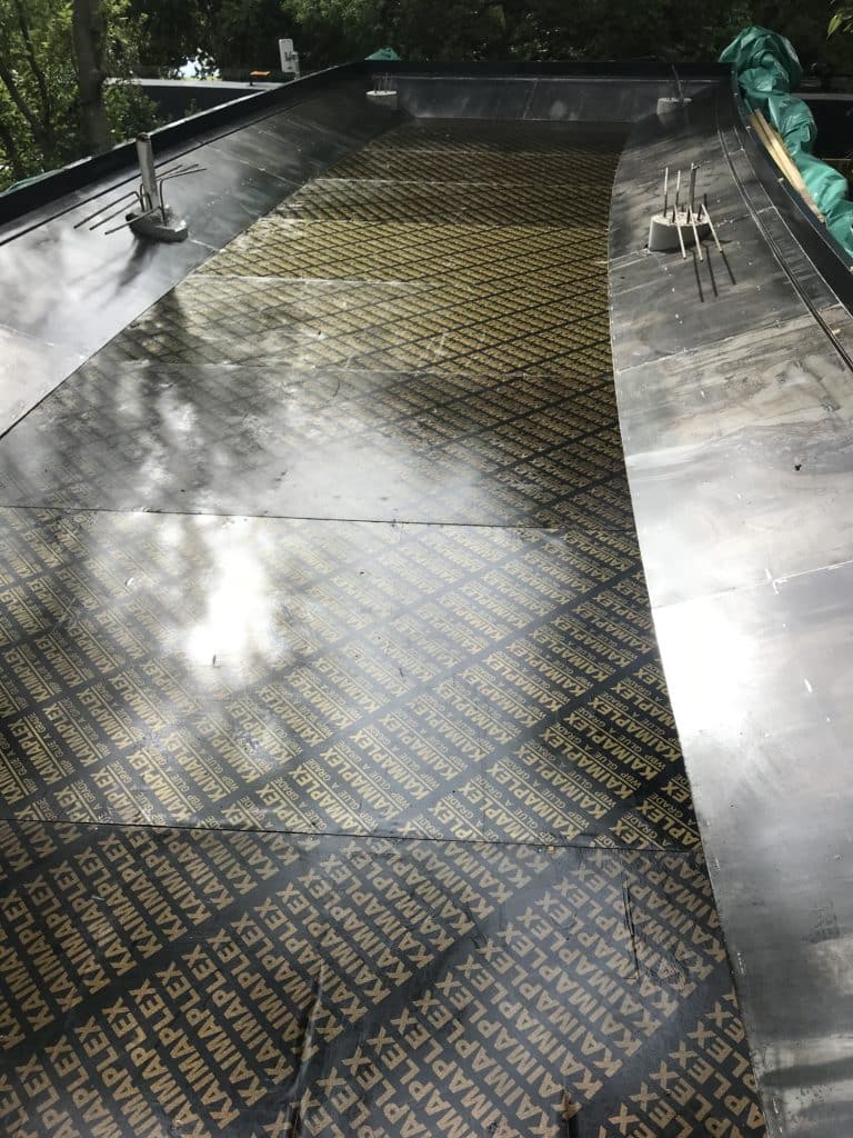
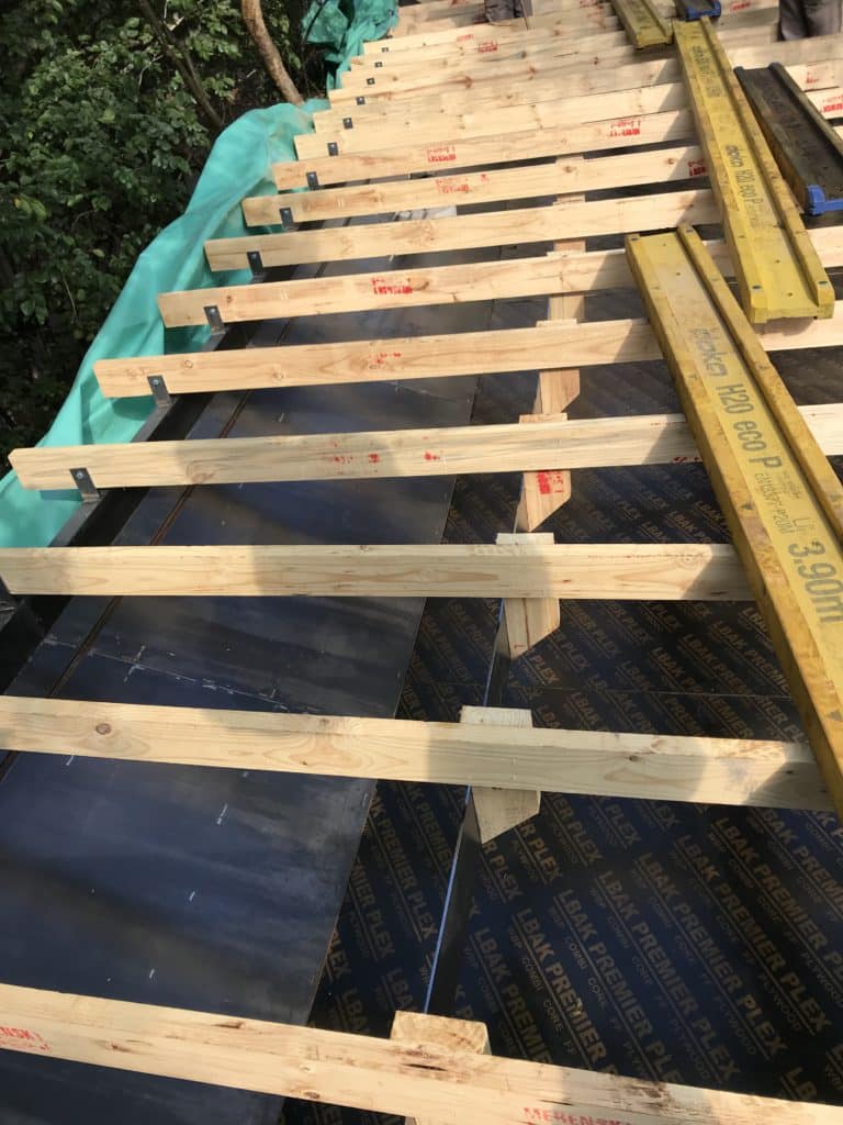
Creating the planter on top
Creating the planter recess on top of the roof required a ‘flying shutter’ which followed the curve of the roof. To form this, I had lugs welded to the top sides of the steel formwork at around 400mm intervals to which 114×50 SAP runners were bolted. To these runners, we fixed a 170mm wide steel flat bar which we could bend to form the ‘flying shutter’.
Unforeseen problems…
As with any construction project, regardless of how much thought and planning you put into a project, there are always surprises along the way.
One of these was with the very tall, slender columns. Upon stripping the first two columns we placed, we found horizontal cracks around the circumference of the columns at certain intervals. Something I have never encountered before. After some investigating and careful demolition of the first column, we saw that these were segregation cracks that formed at the stirrups as the concrete was setting.
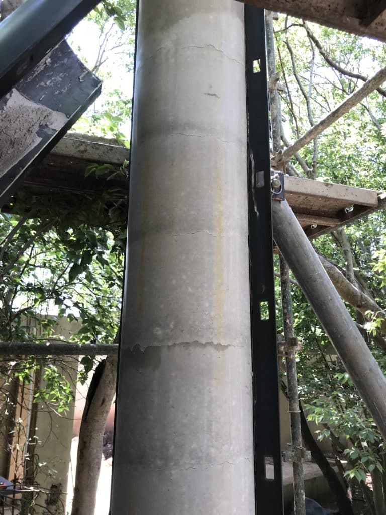
So we demolished the two columns and tried again, with an altered concrete mix with a higher segregation resistance. Upon stripping the formwork, the same cracks were still present.
The only alternative now was to negotiate with the engineer to increase the rebar cover from 25mm to 60mm to give the concrete space to settle between the rebar and the side of the formwork. The engineer eventually agreed, and so we set off, re-bending 386 stirrups to the smaller diameter.
After the third try and four demolished columns, we finally had our first two columns poured. Thereafter everything went pretty much as planned. The tolerance we built into the steel formwork for the columns was pushed to the maximum in one of the roof sections, but we always had enough play to work with that the steel formwork fit around the columns.
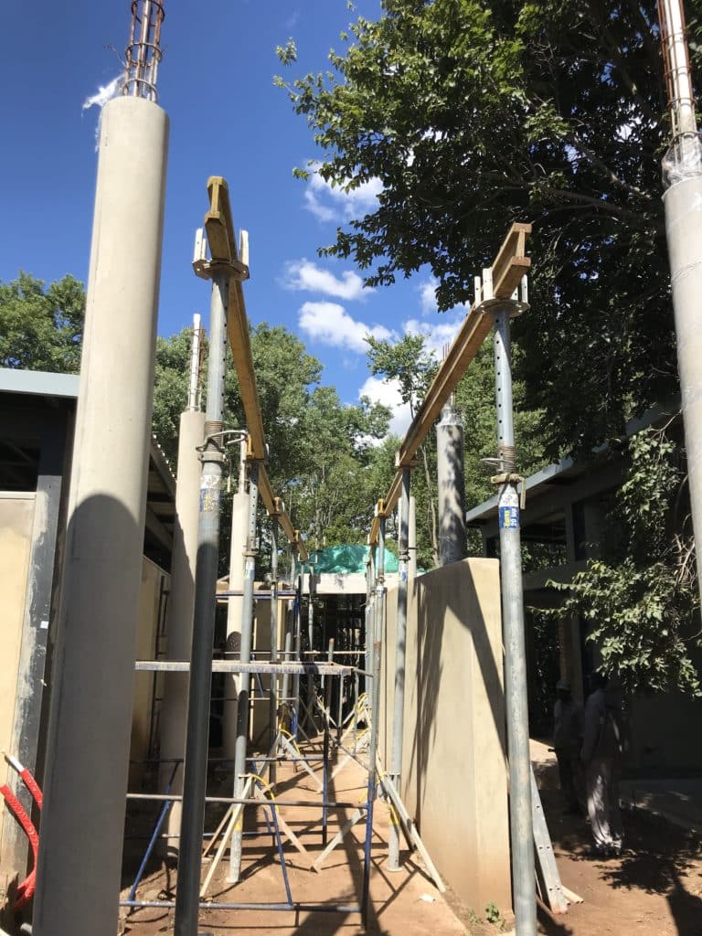
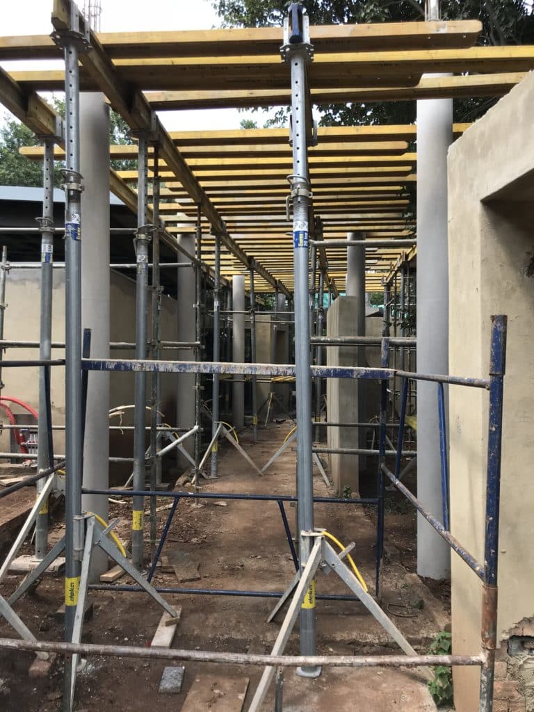
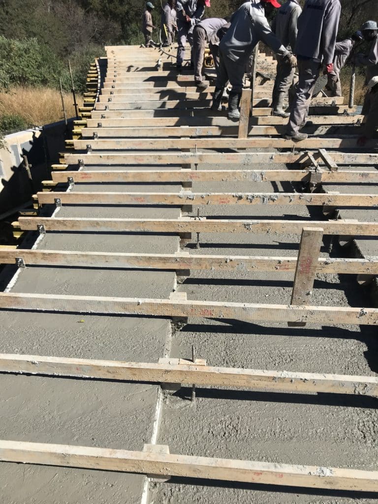
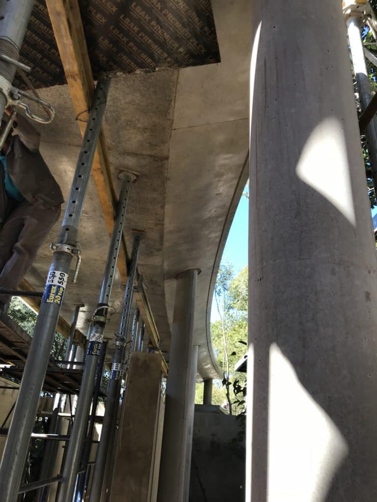
Construction progress
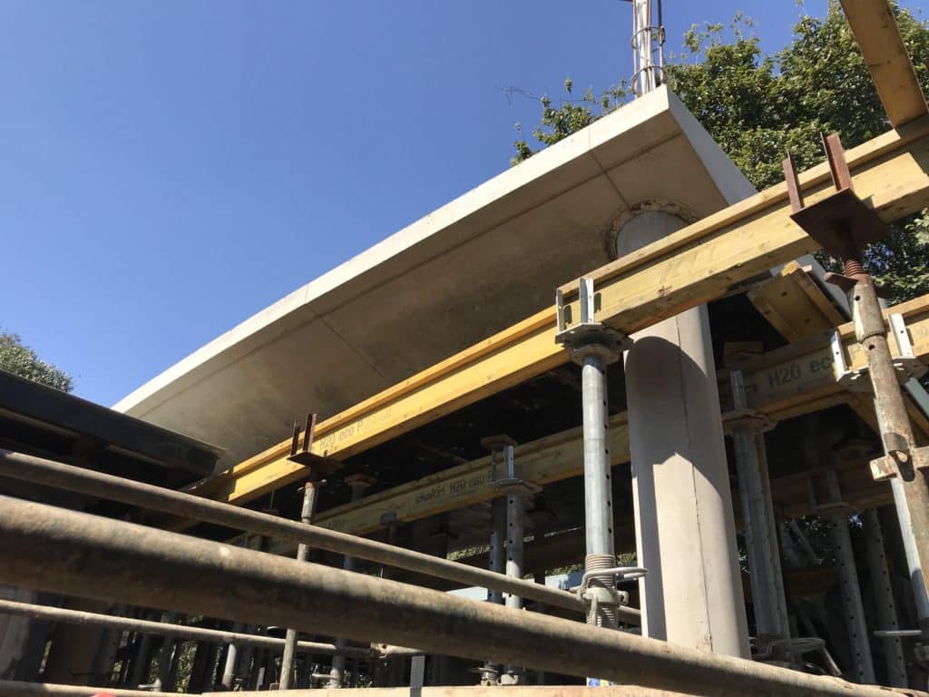
Fresh out the mould as the formwork is being stripped
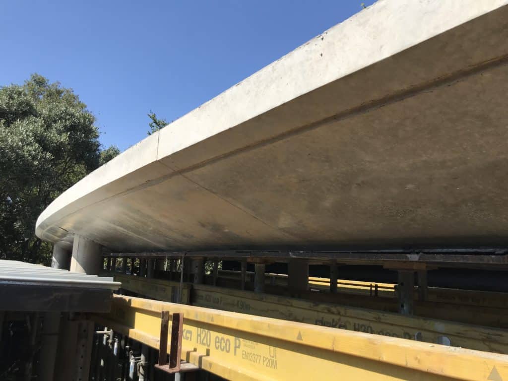
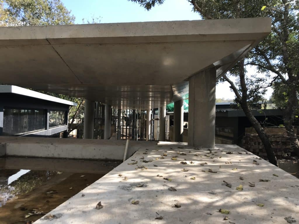
The end product
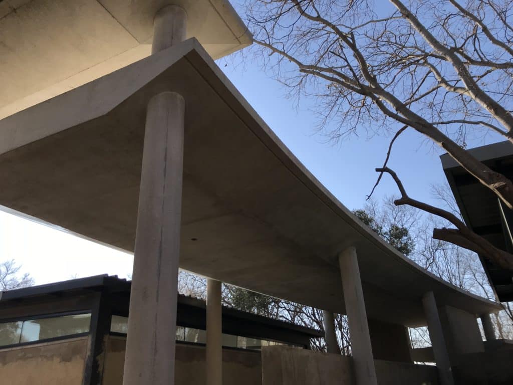
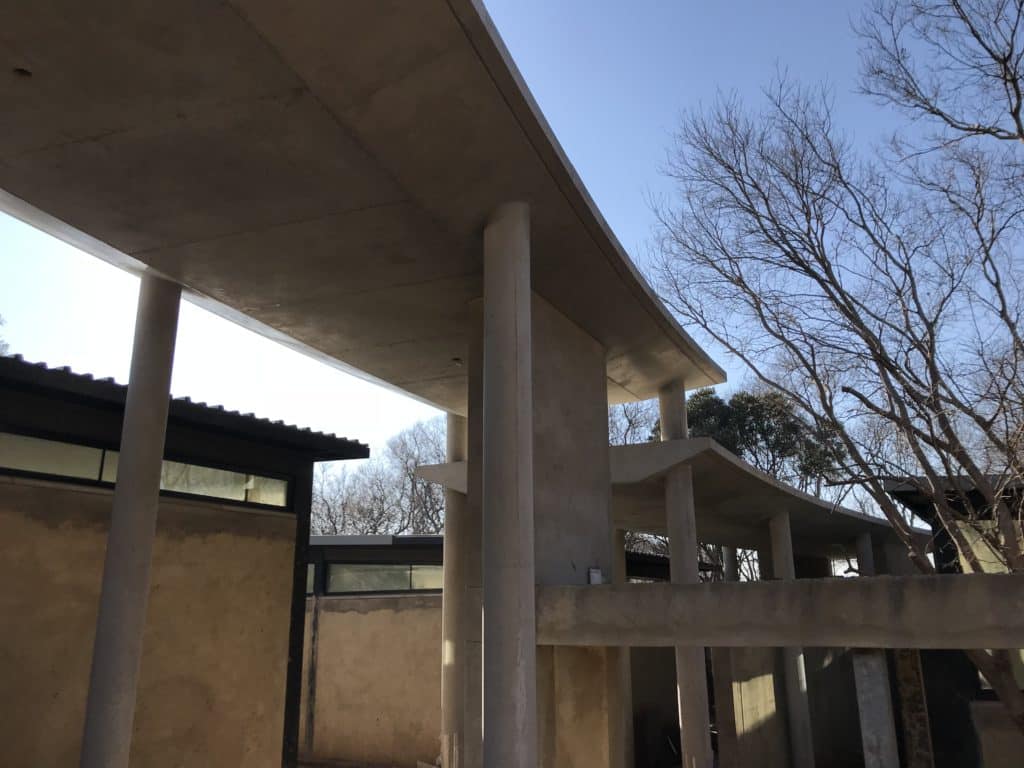
As can be seen from the photos, the only patching we had to do was around the columns to remove the marks left by the ‘compensation rings’.
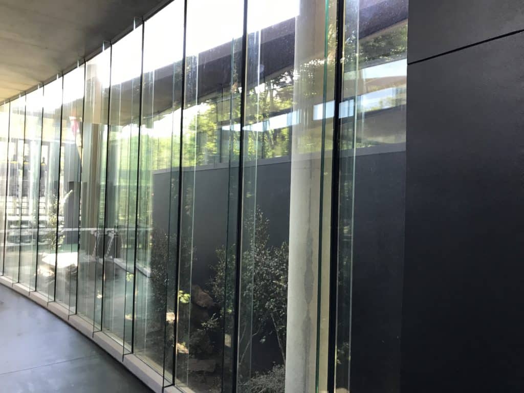
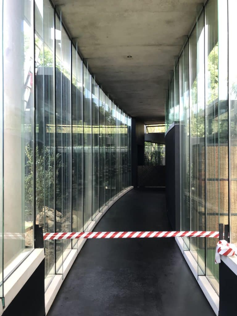
To finish off these passages, we moulded custom copings to accommodate sectional glazing that went from floor to ceiling with stiffening webs in between each section of glazing. I will cover my process of making custom concrete copings on-site in a separate blog, so keep a lookout for that.
Conclusion
Although there was nothing really out of the ordinary with this build, I hope you learned something about working with tolerances, planning soffit board layouts, and enjoyed seeing the finished product, as much as I enjoyed building it!
Should you require any assistance with your next concrete project or would like to get more information about our moulded concrete solutions, feel free to contact me at anton@elemento.net.za